Tutorial 2 - RTL Compiler Synthesis & Synthesized Simulations
Updated 2020-09-06
This document covers how to setup the Linux environment to use Cadence Encounter RTL Compiler, configuring TCL file, synthesizing our SystemVerilog design, and simulating the synthesized design in ModelSim. This document is a revision of Dr. Shekhar’s tutorials1. However, we are using PDK 15 nm models, so certain parts are different.
Environment Setup
In this section, we will setup the Linux environment ready for the tools, take care of licensing issues, and start using the tools.
Working Directory
We will create a working directory where our Cadence-based project files and other generated files will live. One option is to make a Cadence_StudentNumber directory in your home directory — where StudentNumber is your UBC student number or ECE account ID. Once you made the directory, descend into that directory:
mkdir Cadence_StudentNumber
cd Cadence_StudentNumber
Next, while inside the Cadence working directory, source the install script to set up the environment. This creates subdirectories for various tools, defining paths, environment variables, sets up licensing.
source /CMC/kits/AMSKIT616_GPDK/underg_install.csh
Setup Local
Before we continue, there is another setup_local.csh script we need to source located in our working directory.
source setup_local.csh
File Preparation
In this section, we will learn how configure various files required for a synthesis.
First, from your Cadence working directory, descend into the subdirectory called synth. This will be our working directory for synthesis related tasks. Notice that inside the synth directory, there are two more subdirectories called in and out. They are where input source files and generated output files should be placed, respectively.
SystemVerilog Files
Copy the SystemVerilog files we had for previous tutorial (with the exception of testbench files — since those are not synthesizable) into the in subdirectory.
Library Files
There exists kit designers provided .lib files which include required information regarding standard cells. No actions are required for these files — but keep in mind where they are as we need them to construct our TCL instructions file.
-
Path:
/ubc/ece/data/cmc2/kits/ncsu_pdk/FreePDK15/NanGate_15nm_OCL_v0.1_2014_06_Apache.A/front_end/timing_power_noise/CCS
-
Required File: NanGate_15nm_OCL_worst_low_conditional_ccs.lib
SDC File
The SDC file is a text file with .sdc as extension. It includes the description of the clocks and other timing constraints used in the design.
Inside the in subdirectory, create a new file called timing.sdc, add the following lines show in Code 1 into the file:
current_design <design_name>
create_clock [get_ports {<clock_port_name>}] -name <clock_name> -period <clock_period_ns> -waveform {<rise> <fall>}
Where we need to replace these parameters:
<design_name>is the module name of the top level module.<clock_port_name>is the port name for the clock port of the top level module. (e.g. “clk”).<clock_name>is the clock instance name — we can set this toclk.<clock_period_ns>is the clock period in nanoseconds.<rise>is the clock rising edge offset, we set this to0.<fall>is the clock falling edge offset, we set this to50so we have a 50% duty cycle wave/square wave.
When completed, our SDC file should look something like Code 2.
current_design up_counter
create_clock [get_ports {clk}] -name clk -period 100 -waveform {0 50}
TCL Instructions File
The Tool Command Language (TCL) instructions file contains a sequence of instructions we need to execute in the RTL compiler environment. Having it as a file is convenient because we don’t need to type each and every command manually.
While it is highly recommended you go through the following steps to understand what we are doing in the TCL file, one can skip to Completed TCL File if they just want to copy-and-paste.
Writing the TCL File
Create a new file in the in subdirectory called compile.tcl, and follow the steps:
-
In the empty TCL file, insert the following line to include utility script:
include load_etc.tcl -
Set our top-level design variable, which we use later for file output. Append the following:
set DESIGN up_counter -
Set synthesis and mapping effort, as well as synthesis working directory. Append the following:
set SYN_EFF medium set MAP_EFF medium set SYN_PATH "." -
Set PDK path and library file for the PDK library (see Library Files section). Append the following code:
set PDKDIR /ubc/ece/data/cmc2/kits/ncsu_pdk/FreePDK15/ set_attribute lib_search_path /ubc/ece/data/cmc2/kits/ncsu_pdk/FreePDK15/NanGate_15nm_OCL_v0.1_2014_06_Apache.A/front_end/timing_power_noise/CCS set_attribute library {NanGate_15nm_OCL_worst_low_conditional_ccs.lib} -
Read in our SystemVerilog files (remove the
-svflag if we want to read regular Verilog files). Append the following:read_hdl -sv ./in/up_counter.svNote: If there are multiple SystemVerilog files, just call the
read_hdlcommands for each file in reverse-hierarcharical order.For example, if the top level module
Tominstantiates submoduleSamandSierra, then execute the command in the order of:Sam, thenSierra, thenTom:# Example for the above Note: read_hdl -sv ./in/sam.sv read_hdl -sv ./in/sierra.sv read_hdl -sv ./in/tom.sv -
Specify the top level module by using
elaboratecommand. Append the following:elaborate $DESIGNNotice that where we are using the
$syntax to use the design name variable name we have defined earlier. -
Check the design to ensure we don’t have any problems. Append the following:
check_design -unresolved -
Read in the timing constraints file. Append the following:
read_sdc ./in/timing.sdc -
Synthesize generic cell. Append the following:
synthesize -to_generic -eff $SYN_EFF timestat GENERIC -
Synthesize to gates. Append the following:
synthesize -to_mapped -eff $MAP_EFF -no_incr timestat MAPPED -
Run incremental synthesis and insert Tie-High and Tie-Low cells. Append the following:
synthesize -to_mapped -eff $MAP_EFF -incr insert_tiehilo_cells timestat INCREMENTAL -
Generate report files to the out subdirectory. Append the following:
report area > ./out/${DESIGN}_area.rpt report gates > ./out/${DESIGN}_gates.rpt report timing > ./out/${DESIGN}_timing.rpt report power > ./out/${DESIGN}_power.rpt -
Generate and export mapped Verilog files to be used in Cadence Encounter and ModelSim. Append the following:
write_hdl -mapped > ./out/${DESIGN}_map.v -
Generate and export the timing constraints file to be used in Encounter. Append the following:
write_sdc > ./out/${DESIGN}_map.sdc -
Generate and export the timing constraints file to be used in ModelSim. Append the following:
write_sdf > ./out/${DESIGN}_map.sdf -
Status update and exit. Append the following:
timestat FINAL
puts "Exiting . . ."
quit
Completed TCL File
After that, your TCL instructions file should look something like Code 3 (at least for our up_counter example). Note that in this example TCL file, we’ve added puts statements which print messages to the screen to improve user experience.
# Include TCL utility scripts
include load_etc.tcl

# Timestamp
date

# Print status
puts "\n\n> Setting up Synthesis Environment . . ."

# Top level design name variable
set DESIGN up_counter

# Set synthesis effort, mapping effort, and working directory
set SYN_EFF medium
set MAP_EFF medium
set SYN_PATH "."

# Set PDK Library
set PDKDIR /ubc/ece/data/cmc2/kits/ncsu_pdk/FreePDK15/
set_attribute lib_search_path /ubc/ece/data/cmc2/kits/ncsu_pdk/FreePDK15/NanGate_15nm_OCL_v0.1_2014_06_Apache.A/front_end/timing_power_noise/CCS
set_attribute library {NanGate_15nm_OCL_worst_low_conditional_ccs.lib}

# Read in user Verilog files (add -sv flag for SystemVerilog files)
read_hdl -sv ./in/up_counter.sv

# Elaboration validates the syntax (elaborate top-level model)
elaborate $DESIGN

# Status update
puts "> Reading HDL complete."
puts "> Runtime and memory stats:"
timestat Elaboration

# Show any problems
puts "\n\n> Checking design . . ."
check_design -unresolved

# Read timing constraint and clock definitions
puts "\n\n> Reading timing constraints . . ."
read_sdc ./in/timing.sdc

# Synthesize generic cell
puts "\n\n> Synthesizing to generic cell . . ."
synthesize -to_generic -eff $SYN_EFF
puts "> Done. Runtime and memory stats:"
timestat GENERIC

# Synthesize to gates
puts "\n\n> Synthesizing to gates . . ."
synthesize -to_mapped -eff $MAP_EFF -no_incr
puts "> Done. Runtime and memory stats:"
timestat MAPPED

# Incremental synthesis
puts "\n\n> Running incremental synthesis . . ."
synthesize -to_mapped -eff $MAP_EFF -incr
puts "\n\n> Inserting Tie Hi and Tie Low cells . . ."
insert_tiehilo_cells
puts "> Done. Runtime and memory stats:"
timestat INCREMENTAL

# Generate report to files
puts "\n\n> Generating reports . . ."
report area > ./out/${DESIGN}_area.rpt
report gates > ./out/${DESIGN}_gates.rpt
report timing > ./out/${DESIGN}_timing.rpt
report power > ./out/${DESIGN}_power.rpt

# Generate output verilog file to be used in Encounter and ModelSim
puts "\n\n> Generating mapped Verilog files . . ."
write_hdl -mapped > ./out/${DESIGN}_map.v

# Generate constraints file to be used in Encounter
puts "\n\n> Generating constraints file . . ."
write_sdc > ./out/${DESIGN}_map.sdc

# Generate delay file to be used in ModelSim
puts "\n\n> Generating delay file . . ."
write_sdf > ./out/${DESIGN}_map.sdf

# Status update
puts "Synthesize complete. Final runtime and memory:"
timestat FINAL

# Done
puts "Exiting . . ."
quit
Synthesis
In this section we will run the synthesis tool. At this point, all of our input files (inside the in subdirectory) should be ready for synthesis.
Make sure we are in the synthesis working directory (…/Cadence_StudentNumber/synth). Then source the setup_local.csh to reset our environment and go into the RTL Compiler environment using the command rc:
source ../setup_local.csh && rc
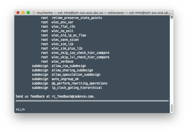
The licensing checkout process begins — this will take a few seconds. Once licenses are checked out and validated, we enter the RC environment as shown in Figure 1. In the RC environment, source the TCL file we created in the previous section:
source ./in/compiler.tcl
The RTL Compiler will execute the instructions provided in the TCL file and will generate the artifacts — the reports and output files — in the out subdirectory.
The generated design files are as follows:
.v: Verilog file with the new gate level description of the synthesized system..sdc: Constraints file which includes the timing constraints of the system..sdf: Constraints file which includes the timing information about the used standard cells.
The generated reports are as follows:
- Area report
- Used cells statistics report
- Timing report
- Power consumption report
The generated files will be used in the coming steps in the digital flow. The generated reports are important to assist one in making sure that the system meets the required specifications.
Simulate Synthesized Design
In this section we will take the generated artifacts from previous section regarding synthesis and put them to the test — in ModelSim simulations. Review previous ModelSim tutorial on basic ModelSim usage.
Compile Files
Start by copying the output .v file from the synthesis output directory into our ModelSim project directory. You may need to modify the module name or remove the un-synthesized SystemVerilog file to avoid name conflicts.
Next, add the required PDK Verilog file to the project. This file incldues the behavioural description of the standard cells. Go to the Project tab and then go to Project → Add to Project → Existing File… and navigate and select the following file:
/ubc/ece/data/cmc2/kits/ncsu_pdk/FreePDK15/NanGate_15nm_OCL_v0.1_2014_06_Apache.A/front_end/verilog/NanGate_15nm_OCL_functional.v
Then, compile all files and ensure all files compiles successfully.
Testbench
Modify the testbench files (if required) to instantiate the newly generated mapped module. Because we need to see if the synthesis is successful, we should leave the rest of the testbench untouched — and expect identical waveform outputs.
Simulation Options
Follow the same steps outlined in the previous ModelSim tutorial to begin simulation. However, on Start Simulation window, go to SDF tab, and click Add. An Add SDF Entry window will appear like shown in Figure 2. Click on Browse and then navigate and select the .sdf file from your synthesis output directory.
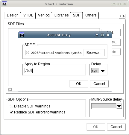
Enter the name of the top-level module in the test-bench in the Apply to Region text field and click OK.
Back in the Start Simulation Window, enable the Reduce SDF errors to warnings checkbox.
Run Simulation
Follow the same steps outlined in the previous ModelSim tutorial to setup your waveforms and run simulation. Ensure the waveform output is as expected compared to the orignal, unsynthesized waveform output.
Below in Figure 3 is the ModelSim simulation window. Notice on the Instance list on the left-side panel, the DUT (up_counter module) is now consists of standard design units (DFFs, Inverters, etc) instead of abstract “initial” or “always” blocks.
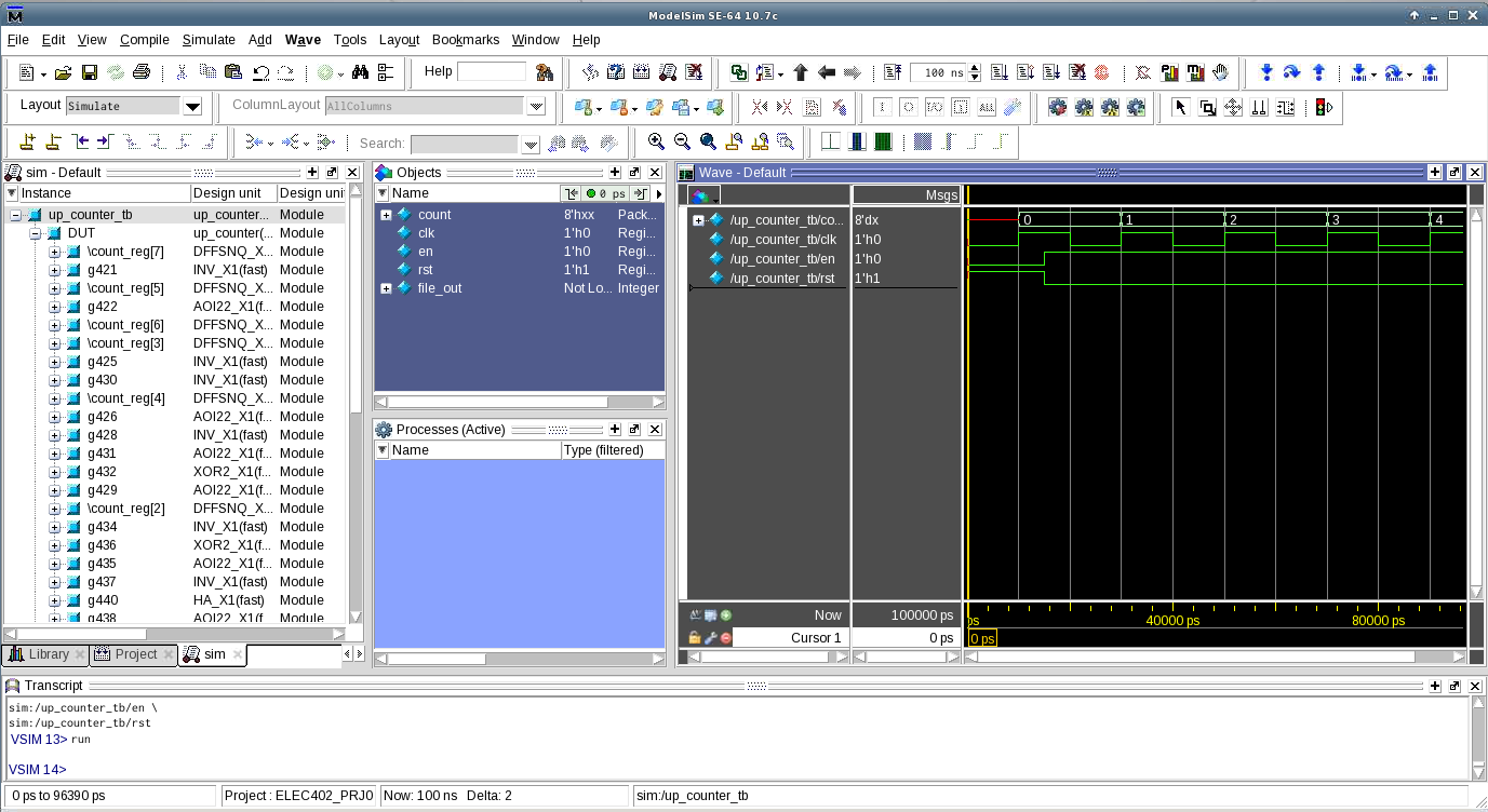
On the righthand side, the Wave window shows testbench signals as expected:
- The clock is toggling every 10 time-units (recall from our testbench, we set our time-unit to be 10 ns or 10,000 ps).
- At time-unit 15, the
rstsignal goes LOW, andensignal goes HIGH. - Afterwards, on each positive clock edge, the 8-bit output
countincrements by 1.
As we can see, the waveform output of the synthesized simulation is identical to the unsynthesized simulation we saw in the previous tutorial.
This is to be expected as we defined our clock period in the .sdc file to be 100 ns (frequency of 10 MHz). Using a high-frequency clock would likely lead to small differences between the ideal design (unsynthesized simulation) and the synthesized design.
Conclusion
👏 Congratulations on completing the RTL Compiler Synthesis and Synthesized Simulations tutorial. If you have any questions or concerns, please contact us using the information found on Canvas course page.
If you’re ready to move on, checkout Cadence Virtuoso Tutorial.
-
Sudip Shekhar, University of British Columbia, “CAD Tutorials”: http://sudip.ece.ubc.ca/cad-tutorials/ ↩