Project 2 Report - Synthesis
Updated 2019-10-06
In this project, I continued work from project 1. In particular, I took the FSM built in the first project and used CAD tools to synthesize the design into stanard cells.
Mapped Verilog
I used Cadence Encounter RTL Compiler to generate a mapped SystemVerilog code. Since the file contains 1,132 lines of code. It will be attached as a separate file. It can also be accessed on my GitHub here.
Design Changes
A small set of changes regarding the bit width of I/O of the decoder modules required changing. Since there were bits on the bus that were never used, ModelSim would confuse it with high-impedance (z signals).
I also had to change the bit-width for states from 5-bits to 4-bits since we were using 12 states to also mitigate the highest bit left on high-impedance.
Otherwise, the overall design and the operation of the FSM remained identical to project 1.
Here is an example diff of the changes made:
- enum logic[4:0] {
+ enum logic[3:0] {
      ST_IDLE,                /* [1]  The idle / reset state */

      ST_APERTURE_PRIORITY,   /* [2]  The default home state for aperture priority mode */
      ST_SHUTTER_PRIORITY,    /* [3]  The default home state for shutter priority mode */
      ST_MANUAL,              /* [4]  The default home state for manual exposure mode */

      ST_INC_FSTOP,           /* [5]  State for increasing f-stop number */
      ST_DEC_FSTOP,           /* [6]  State for decreasing f-stop number */
      ST_INC_SHUTTER,         /* [7]  State for increasing shutter speed */
      ST_DEC_SHUTTER,         /* [8]  State for decreasing shutter speed */

      ST_CALC_SHUTTER,        /* [9]  Intermediate state to caluclate shutter speed needed */
      ST_CALC_APERTURE,       /* [10] Intermediate state to caluclate aperture needed */

      ST_WAIT_SHUTTER,        /* [11] State for waiting for the shutter to open and close */
      ST_DONE                 /* [12] state for outputting shutter */
  } current_state, next_state, prev_mode_state;
RTL Compiler Reports
The RTL compiler outputs various reports regarding area, power, timing, and gates. For this project, we are concerned with the area.
Area Report
This is inside of fsm_area.rpt:
============================================================
  Generated by:           Encounter(R) RTL Compiler RC14.13 - v14.10-s027_1
  Generated on:           Oct 05 2019  01:46:46 pm
  Module:                 fsm
  Technology library:     slow_vdd1v0 1.0
  Operating conditions:   PVT_0P9V_125C (balanced_tree)
  Wireload mode:          enclosed
  Area mode:              timing library
============================================================

       Instance        Cells  Cell Area  Net Area  Total Area  Wireload
----------------------------------------------------------------------------
fsm                      634       1399         0        1399    <none> (D)
  mul_261_30             216        496         0         496    <none> (D)
  mul_261_52             199        476         0         476    <none> (D)
  COUNTDOWN_MODULE        62        127         0         127    <none> (D)
  SHUTTER_SETTING_FF       6         26         0          26    <none> (D)
  APERTURE_SETTING_FF      6         26         0          26    <none> (D)
  SHUTTER_DECODER         13         14         0          14    <none> (D)
  FSTOP_DECODER           13         14         0          14    <none> (D)

 (D) = wireload is default in technology library
The total cell count is 634.
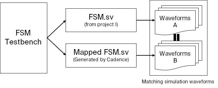
ModelSim Tests
A derived testbench (from project 1) is used for the generated Verilog. To run the testbench in ModelSim. I ensured that the optimization for internal signals is set to off for debugging purposes such that the assert statements could function correcty as it is used to check states.
I also compared the simlation/testbench output waveforms to the reference waveforms from project 1. The output is matching to ensure everything is working correctly.
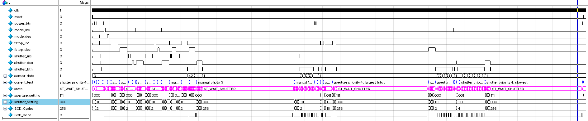
Visual Waveform of Mapped Verilog
The details regarding the tests shown in the waveform is already described in project1. So here I will just show the overall output waveform.
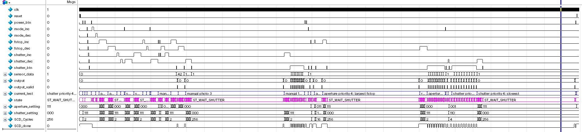
It is a bit harder to see, but I assure that I verified this against the reference waveform. Here is the output waveform from the unmapped (hand-coded) verilog FSM for reference: