Magnetic Field Track Robot
Updated 2017-04-06
A collaborative project by ELEC 291 - Team B6: Nicholas (Scott) Beaulieu, Geoff Goodwin-Wilson, Muchen He, Larry Liu, Lufei Liu, and Wenoa Pauline Teves.
- 1. Introduction
- 2. Investigation
- 3. Design
- 4. Lifelong Learning
- 5. Conclusion
- 6. Bibliography
- Appendix
1. Introduction
Objectives
The objective of this project is to design, build, program, and test an autonomous robot which is controlled using the magnetic field generated by a guide wire.
Specifications
Guideline wire frequency: 16.0 kHz
Guideline wire communication baud-rate: 15.625 (64.00 ms per bit)
Battery life: ~20 minutes (drawing 500mA on a 9V alkaline battery)
Parts List
A detailed parts list is included in the appendix.
Software Features
Robot
- Reads commands sent through via the wire’s magnetic field as binary (self made UART)
- Supports interpretation from binary up to 4 bits
- Supports the following commands (transmitted via binary as mentioned above):
- Stop
- Turn left at the next detected intersection
- Turn right at the next detected intersection
- Track forward
- Track backward
- U-turn (rotates 180 degrees)
- Proximity detection using sonar sensor
- Stops the robot when objects directly in front of the robot is detected
- LED Matrix Visualizer that displays bitmapped pixel art that associates to the command
- Blinker LEDs to simulate turn signal
Guideline Controller
- Generates 16kHz square wave in the guideline wire for the robot to follow
- Sends commands to the robot using binary by switching the 16kHz signal on or off (self made UART)
- Sends the binary for the following commands:
- Stop
- Turn left at the next detected intersection
- Turn right at the next detected intersection
- Track forward
- Track backward
- U-turn (rotates 180 degrees)
2. Investigation
Idea Generation
Our team generated ideas by going through the steps of the design process (i.e. identifying requirements, generating multiple ideas that satisfied these requirements, and choosing the most efficient). In this case, that meant that we wanted our robot to move smoothly, quickly and receive data at the fastest possible frequency.
Ideally, we also wanted designs that were modular, consisting of independent components. This would enable a better work flow by allowing better communication and collaboration within the team as parts of the project would not depend on each other.
Design Investigation
Our team gathered data through online research and testing. We also used the lab tools to gather data, which is expanded on below in Data Collection.
Data Collection
Referring to online data-sheets when building our potential design, we would test expected outputs using tools provided to us in the lab. Below are some of the ways we used the tools in Macleod Lab:
Multimeter We used the multimeter to measure voltages of various components of our circuits-such as the outputs of the operational amplifiers (OP Amps) 1 and the comparators 2 and to check the validity and continuity of our circuit prototypes.
Function Generator We used the function generator to generate square waves through our guide wire to simulate a 16.0 kHz signal in order to test our tracking robot.
Oscilloscope With our capacitance and inductance values; the theoretical resonance frequency was 16.0 kHz. We used the oscilloscope to ensure that this was true.
Power Supply We used the power supply to save batteries and to determine the amount of current that was being drawn out of our circuit at certain voltage levels. The power supply was also used to test our design’s characteristics, such as the speed of the motors, at different levels of power.
Using the same methods outlined above to analyze potential designs, we tested various circuit components. We used the oscilloscope to read the accuracy of our peak detectors, ensuring that the signal was DC, and to debug the output signals throughout the circuit. We then checked with the multimeter to confirm voltages and frequencies.
Data Synthesis
While testing our design, we would observe readings on the oscilloscope and multimeter, values on PuTTy and the physical movement of our robot.
When testing our tank circuits, we would test the outputs before implementing it into our main robot. The most effective way our team tested the tank circuits was to hold the inductor 3 over a wire with current and observe the DC signal displayed on an oscilloscope. From this we observed that the amplitude of the voltage increased very rapidly as the wire was brought closer to the inductor. This was especially apparent as the inductor followed an exponential curve relative to distance, and would increase rapidly as it gets within millimeters of the inductor.
Analysis of Results
Our team appraised the validity of conclusions through the actual execution of our robot. When testing the commands of our robot (forwards, backwards, turns, etc), we agreed with our design when the robot would execute our instructed command throughout a consistent number of test cases. This is explained further in Section 3 under Solution Assessment.
3. Design
Use of Design Process
Using the design process, we generated multiple ideas for potential designs. This gave our team the opportunity to discuss which design we thought would be best for our robot.
Needs and Constraints Identification
The needs for the magnetic track robot were outlined according to our lab manual. In addition to these requirements, some of the needs our team identified for customers are stated below:
- Ease of use: The ability to communicate to the robot through the guide wire should be quick and simple
- Runs smoothly and reliably
Constraints of our robot were also outlined in our lab manual (i.e. the guideline controller operating at a single frequency).
Problem Specification
To increase ease of use, our team implemented an LED matrix 4 that displays the instruction sent to the robot. This allows the user to easily visualize how the robot executes instruction.
Solution Generation
Using Buttons on guideline wire controller is used to send commands:
To communicate with the robot (i.e send a command to turn left, right, stop, 180 degrees), a potential solution was to install buttons 5 on the guide wire generator; each button sending a specific command when pressed.
Using Joystick 6 to send commands:
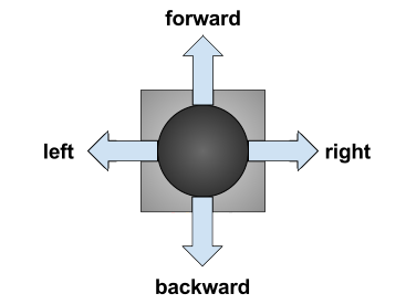
Similarly, we would install a joystick to send commands instead. The direction on the joystick would send the respective command (see Figure 3.1).
Solution Evaluation
The following tables detail our attempts at different configurations for our inductors as well different methods of PWM for our motors.
| Design Concept | Two (2) Inductors | Three (3) Inductors | Four (4) Inductors |
|---|---|---|---|
| Description | Two tank circuits at the front of the robot set at a 45 degree angle | Two inductors parallel to the guide wire and one perpendicular | Two inductors at the front set at a 45 degree angle and two inductors at the back at a 45 degree angle. |
| Forward Tracking | Accurate | Accurate | Accurate |
| Reverse Tracking | Inoperative | Inaccurate | Accurate |
| Intersections | Detects intersections with inductors on a 45 degree angle. Navigates intersections with high error. Trouble understanding current position due to inductor positioning | Detects intersections; Navigates intersections | Detects intersections with inductors on a 45 degree angle; Navigates intersection by measuring voltage on opposite inductors; Able to understand position and correct errors |
| U-Turn | Accurate | Accurate | Accurate |
| Stop | Accurate | Accurate | Accurate |
| Remark | Easiest to implement into software | More hardware than 2 inductors | More accurate tracking when implemented in software due to more inductors tracking positioning of robot on track; Uses the most hardware |
Design Decision We chose to use 4 Inductors because it would track the most accurately and although it uses the most hardware, tracking backwards would be easier because it would be the dual of tracking forwards.
| PWN Function [%] | \(\lambda_L=100\times\frac{V_L}{V_L+V_R}\) | \(\lambda_L=100\times\frac{V_L^2}{(V_L+V_R)^2}\) | \(\lambda_L=75\times\frac{V_L^2}{V_L^2+V_R^2}\) |
|---|---|---|---|
| Description | Simple ratio based on value of opposite inductor and sum of both inductors | Squared ratio | Ratio of Squares multiplied by a lower constant |
| Tracking Forward | Accurate | Inaccurate | Accurate |
| Details | Smooth movement but unable to make sharp turns. Steers off course at sharp turns | Slightly more exaggerated difference between motors than option 1, but is problematic for certain voltage values | Movement is less smooth, but can handle all sharp turns. Multiplying it by a lower constant helped with smoothness. |
Design Decision We chose to use the 3rd ratio because it is the most versatile and exaggerates the difference between the left motor and the right motor. Although the movement is not as smooth, we decided functionality is more important.
Detailed Design
Before starting on any circuits, we had to decide upon a microcontroller to use for our Guideline Wire Generator (A.K.A. Guide wire generator) and Robot Controller. We quickly decided upon the C8051F38C (F38x) 7 for the Robot Controller due to our level of familiarity with it and its overall power to cost ratio.
We then decided upon the ATMega328P8 for the Guide Wire Generator. The reasons associated with the choice are outlined as follows:
- It met the criteria for a different style of microcontroller as outlined in the requirements (8051/AVR)
- It did not need to be soldered to a perfboard
- It did not need to be put into bootloader mode every time it needed to be flashed
- It is a popular microprocessor and has plenty of documentation and support online
- It had a clock speed that, while slower than other available chips, was more than sufficient for our needs
Guideline Wire Controller (Guide Wire Generator)
Overview
The purpose of this controller is to provide a square wave signal at resonance frequency in the guide wire the robot is tracking.
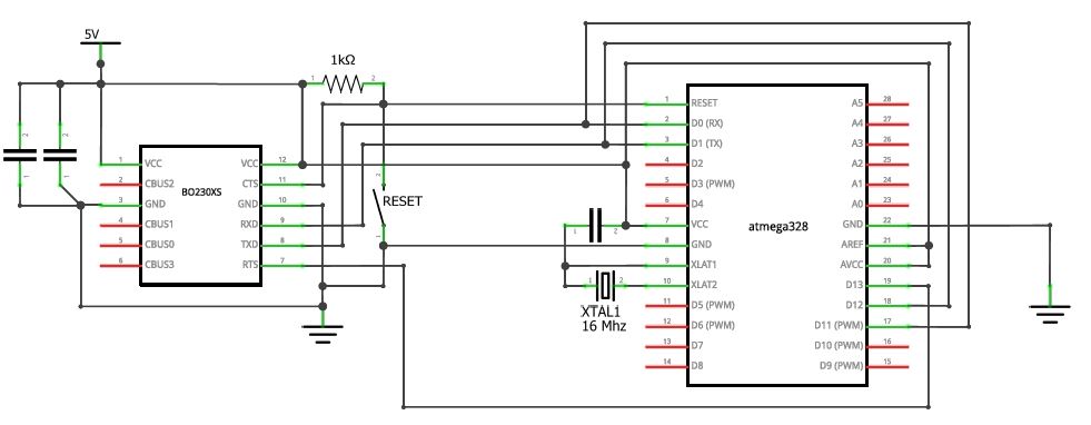
ATMega328P is flashed in the identical fashion as the AT89LP52 from project 1. It is connected to a computer via BO230XS such as in figure B-1. One exception is that ATMega328P only needs the ‘reset’ button as the microcontroller does not need to be put into bootloader mode manually (mentioned above). This enables much more efficient development flow.
The software for the guide wire generator is split into multiple C files and the files are compiled using avr-gcc and make in CrossIDE.
Signal Generation
ATMega328P has 3 timers/counters: two synchronous timer (Timer 0 and Timer 1) and one asynchronous timer (Timer 2). Timer 0 is configured to raise an interrupt at 32.0 kHz. By simply toggling the digital pin 9 (pin D9 in figure B-1 in the appendix) on every Timer 0 interrupt, a 16.0 kHz square wave is generated in the guide wire.
Timer 0 interrupts has the highest priority out of all other timers. This ensures that a consistent 16.0 kHz is transmitted regardless of other functions in the program onboard.
Guide Wire Communication
We are prohibited to communicate with the guide wire tracking robot via wired communication such as direct control, SPI, etc. We are also prohibited from using RF (wireless) communication such as bluetooth, WiFi, infrared, etc. Thus, commands are sent to the robot through the guide wire. When proper input is given by the user, commands are sent through the guide wire every 1 second.
To start sending commands, which are comprised of bits, the 16.0 kHz is first turned off for 64.0 ms. This counts as a ‘0’ bit and tells the track robot to start receiving bits. Then the 16.0 kHz is turned back on for 64.0 ms to synchronize timing on the track robot, allowing the following bits to be read consistently.
The next three bits are the “real” data bits that contains the command code. Since we are sending 6 commands, 3 bits (maximum 8 different commands) are deemed appropriate. The 16.0 kHz signal will be turned on or off depending on if the bit that is currently being sent is 0 or 1. Their transfer rates are all also 64.0 ms per bit.
User I/O
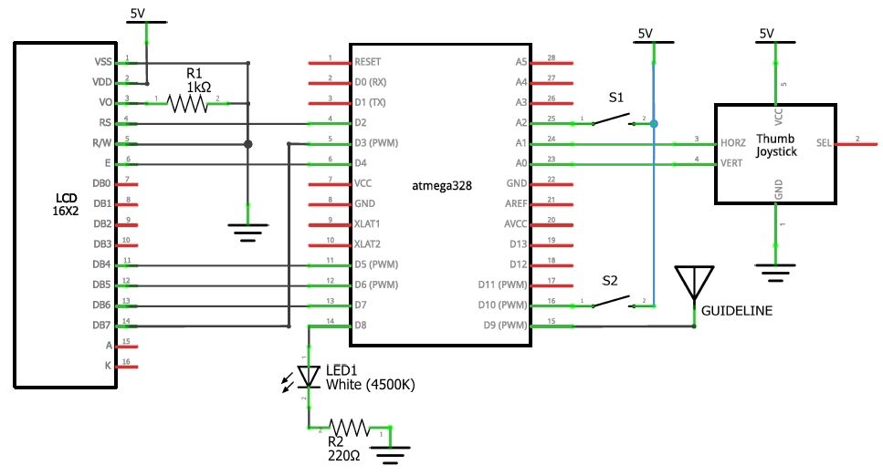
User determines the commands being sent to the robot using buttons and a joystick. The joystick is basically an assembly of two potentiometers and they are connected to Analog 0 (A0) and Analog 1 (A1) pins on the ATMega328P. The x-axis and y-axis analog signal is read by the onboard ADC. Two buttons are connected to two digital input pins for two more commands.
An LCD is attached to the guide wire generator to display the current command being sent. If no command is given, the LCD will display “Awaiting commands”. The attached LED also strobes the individual bits when the microcontroller is transmitting a command.
Magnetic Field Tracking Robot
Tank Circuit
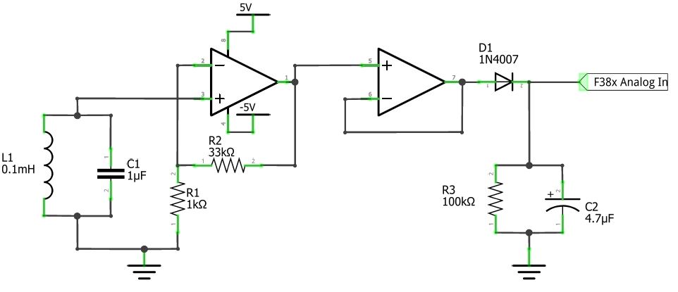
We used 1.0 µF capacitors in our LC (tank) circuits because they were inexpensive and readily available. To ensure that the signal picked up by the inductors would be the same as the generated signal, we used the formula for resonance frequency as shown below to calculate a guide wire frequency of 16.0 kHz.
\[f=\frac{1}{2\pi\sqrt{LC}}\]To increase the resolution of the data we received, we amplified the output voltage from each tank circuit by a factor of \(\alpha=34\) using the formula, \(\alpha=1+\frac{R_2}{R1}\). To capture only the needed peak voltage data points we built a peak detector to create a DC signal of peak voltage that was then read by the microcontroller.The final diagram for the combined Tank, Op Amp and Peak Detector circuit is included in the appendix.
Commands Interpretation
Hardware
In order to receive commands quickly and consistently, we chose to use a digital input rather than an analog input (ADC reading). The chosen software algorithm required the following: the receiver must receive commands at 15.625 Hz (64.0 ms per bit) , and the input voltage must meet the requirements for a digital reading (0 V for logic 0 and 5 V for logic 1). Based on these two requirements, we designed our receiver using a combination of two comparators and one rectifier 9 circuit. The diagram for the receiver is shown in the appendix.
The first comparator has two functions. First, it transforms a sine wave to a steady square wave. Second, and more importantly, it separates the current from other circuits (e.g. peak detector). We found through testing that the rectifier drains current from the circuit and had a large negative effect on peak detector readings when tested without this comparator.
The rectifier transforms the AC square wave to a DC signal. The AC square wave at 16.0 kHz must be smoothed out by a capacitor to a steady DC signal. At the same time, the capacitor must also discharge fast enough to differentiate the “on” and “off” DC signals from turning on and off the AC square wave at 15.625 Hz. After testing various options, we concluded that using 4.7 µF capacitor was the best fit. Command transmissions from the guide wire controller were also slowed down from 100 Hz to 15.625 Hz.
Another comparator was used to boost the maximum voltage of the rectifier output from 2.2 V to 5 V in order to properly indicate logic 1 while maintaining the same frequency.This allowed us to meet the software requirements without compromising any other parts of the circuit.
Software
Our initial design for receiving commands uses UART. However, we found that determining the baud rate for transmitting data is difficult since UART acts as a black box to us. Implementing UART required several issues to be addressed, including noise. This plan requires ample research effort so for the sake of time, we decided to choose the method described below.
Each incoming command from the guide wire begins with a logic 0 detected by an input from the comparator. This triggers the robot to actively read the binary sequence that follows. Commands are read through sampling. Each binary bit is sent for a period of exactly 64.0 ms, and the most accurate way to read the bit is at the midpoint of 32.0 ms.
There is a logic 0 bit followed by a logic 1 bit which acts as a accurately timed trigger before each command. To offset the delay of polling for logic 0, the robot will wait for a logic 1 once the function has been triggered. This essentially synchronizes the robot with the guide wire controller.
Next, the function will wait for 96.0 ms (1.5 times 64.0 ms) to be at the center of the next bit, and 64.0 ms to be at the center of each following bit. The function reads 4 consecutive bits, stores them into a single 8-bit variable, and compares it against the database of commands. Finally, a new command is returned only if it matched with a known command.
This method allowed us to easily adjust the code to match the baud rate of transmitted data unlike UART.
Robot Controller
| States | Description |
|---|---|
| 1 | Tracking forward |
| 2 | Tracking backward |
| 3 | Stopped |
| Command | Received Signal | Bits | Description |
|---|---|---|---|
| 0 |  |
11-111 | No command |
| 1 |  |
01-001 | Turn left at the next detected intersection |
| 2 |  |
01-010 | Turn right at the next detected intersection |
| 3 |  |
01-011 | Switch to tracking forward |
| 4 |  |
01-100 | Switch to tracking backward |
| 5 |  |
01-101 | U-Turn (turn 180 degrees) |
| 6 |  |
01-110 | Stop |
We classified every function of the robot as either a state or a command as described in the table above. Commands take higher priority than states. The robot will check if there are any incoming commands from the guide wire generator (as explained in the previous section) and then enter the function associated with its current state. The robot then executes the current command, resets the command to 0, and loops back to the function associated with its current state. In the case of left and right turns, the robot cannot execute the functions immediately so the command is kept and executed if an intersection is sensed. The command is returned to 0 when the turn has occurred or the command can be overwritten by another sent command.
In each loop, the robot checks for sonar readings. If an object is picked up by the sonar to be less than 7 cm away, the robot will execute the stop function as a safety measure and wait until the object has been removed to resume its previous state.
Also in each loop, the current command of the robot is displayed onto an LED matrix. The state of “stopped” is also displayed onto this LED matrix. In the case of left and right turns, signal LED lights are set to blink.
While the command is 0 the robot is also searching for intersections. The combined high voltages of the inductors signal an intersection and trigger a function that ensures the robot continues straight through the intersection.
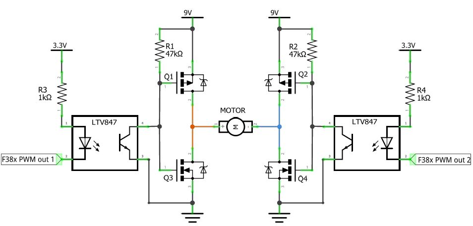
Motor Adjustments
To run and adjust the power output to our motors, we built two H-Bridge circuits. To control the speed of the motors, we used Pulse-width modulation (PWM). As a result of changing the duty cycle of the square wave outputted to the H-Bridge circuits, the speed of the motors change. The ratio used for PWM is as follows:
\[\lambda_L=75\times\frac{V_L^2}{V_L^2+V_R^2}\]Left and right turn commands are activated by an intersection. The robot first moves straight forwards for 300 ms until it is directly on top of the intersection. Then, one motor is set to 50 PWM forwards while the other is set to 0, allowing the robot to pivot in place. The robot turns for 200 ms in order to move the rear inductors off the current track, and continues to turn until the rear detectors sense the new track. From here, the robot continues on with its current state.
Turns while moving backwards are similar; the difference is that the robot will move backwards to be directly on top of the intersection and the PWM is set in the opposite direction. The command is still dependent on the rear inductors to sense the new track. The rear inductors were chosen to sense the end of a turn because they are farther from the wheels, thus farther from the intersection and reading more accurate voltage values.
When crossing intersections with no current command, the robot should continue forwards. As the intersection interferes with line tracking, it is difficult to predict at which angle the robot will enter the intersection. For example, the robot might sense the intersection while at a 45 degree angle to the line it’s currently tracking and steer off track. In order to prevent this, we assess which rear inductor is higher and turn the robot slightly as it moves through the intersection to adjust. If the right rear inductor has a higher voltage than the left rear inductor, we know the robot is entering the intersection pointing slightly to the right. We then can easily adjust for this by setting the left PWM to 25 and the right PWM to 50 so the robot can resume line tracking properly once it has exited the intersection.
Finally, our function to rotate the robot by 180 degrees sets PWM values to be equal in magnitude but opposite in direction which allows the robot to spin in one spot. The robot spins for 2 seconds, long enough so the sensors are no longer on the track, and then continue until the sensors sense that the robot is once again on track. At this point, the robot will continue with its previous movements.
Solution Assessment
Our team conducted different types of testing to ensure that our design could meet requirements efficiently. Once our final design was built for both the guide wire generator and our robot, we recorded testing data. The data was generated by testing commands sent through the guide wire generator while our robot’s power was supplied by batteries.
We tested for quality of our robot with our Turn Test (see appendix), where we scored our robot’s turns between 1-10. Scoring below a 5 indicated a failure (i.e did not make the turn), and above 5 indicated a pass. For example, a score of 6 meant our robot made the turn but drove off track and readjusted itself, while a 10 meant the robot executed a perfect turn.
We tested the consistency of our robot with a Consistency Test (see appendix). This test was pass or fail, depending on whether the robot’s execution of a command was successful.
A strength of our design was consistency. When our robot was at its prime voltage level (around 8 V), the rate of successful execution was 100% (out of 5 trials).
A weakness of our design was accuracy of turns at different levels of voltage. When the voltage levels were too high (i.e after replacing the battery in our robot), the robot would overshoot turns due to the motors drawing in more current. Similarly, low voltage levels would get our robot stuck during turns due to the motors being too weak to carry the robot’s wheels across the wire.
4. Lifelong Learning
We learned how to test for broken MOSFETs through online resources. The steps he used are as followed:
- Use a multimeter set in diode mode
- Connect the gate and drain of the MOSFET to the multimeter
- If a voltage can be read by the multimeter; then a current is running through it and therefore the diode inside must be broken
Additionally, the course ELEC211: Engineering Electro-magnetics was critical for this project; it helped our team better understand magnetic fields, and the course inspired our design decision to place our inductors at 45 degree angles.
5. Conclusion
The foundation of our wire-guided robot was an light aluminum chassis, built to house a breadboard, two motors, inductors, and batteries. Our design features four inductors, two at the front of the robot and two at the back, placed strategically at 45 degrees to the guide wire on the bottom of the chassis to detect intersections, track the wire and navigate intersections both forwards and backwards.
The first breadboard includes circuits to find the amplified peak voltage of each front inductor, H-Bridge circuits for motor control, an F38x microcontroller, and a data transmission comparator circuit.
An additional smaller breadboard is mounted above the first to include peak detector circuits for the rear inductors. Information from all detection circuitry is sent to the F38x where tracking algorithms are used to control the motors’ direction and power.
One final breadboard which is isolated from the main setup includes an ATMega328P microcontroller to send commands through the wire to the robot, and a joystick controller for user command input.
Six different commands can be sent to the robot to execute through the main tracking wire. The robot then recognizes each different command by its binary signature and either stores the command or executes it immediately.
Bonus features include sonar to detect objects on the wire path, an LED matrix which displays the current command the robot is executing, brake lights, running lights, and signal lights for turn commands. The robot is controlled using a knob controller in combination with a push button to execute all 6 commands.
There were various problems encountered and overcome in this project. The major problem was intersection navigation, while minor problems included reliability of peak detection circuitry, and the inductors shorting by touching the aluminum chassis and inducing voltages on each other. The amount of time spent on this project averaged 60-70 hours per person.
6. Bibliography
LiteOn Incorporated,“LTV847 Optocoupler,” LiteOn Incorporated LTV817 Series Datasheet, April. 2010[Revision: K]
National Semiconductor,”LMC7660IN Switched Capacitor Voltage Converter,” LMC7660 Switched Capacitor Voltage Converter Datasheet, Feb. 2005
STMicroelectronics,”L7805CV Positive Voltage Regulator,” STMicroelectronics L78 Series Datasheet, June. 2004[Revised Nov. 2016]
Fairchild Semiconductor International Inc,”FQP8P10 P-Channel QFET MOSFET,” Fairchild Semiconductor FQP8P10 P-Channel QFET MOSFET Datasheet, 2002[Revised Mar. 2013]
Fairchild Semiconductor International Inc,”FQP13N06L N-Channel QFET MOSFET,” Fairchild Semiconductor FQP13N06L N-Channel QFET MOSFET Datasheet, 2001[Revised Nov. 2013]
Appendix
A. Detailed Parts List
Microcontroller
| Qty | Part Number | Description | Manufacturer |
|---|---|---|---|
| 1 | C8051F38C | 8051 microcontroller | Silicon Laboratories, Inc. |
| 1 | ATMega328P | AVR microcontroller | Atmel Corporation |
Robot Assembly
| Qty | Part | Manufacturer |
|---|---|---|
| 1 | Custom waterjet cut aluminum chassis | |
| 2 | GM4 Clear servo motor | Solarbotics |
| 2 | Servo 2.63” x 0.35” wheel | Lynxmotion |
| 1 | 70144 ball caster | Tamiya |
| 4 | AA battery holder | |
| 1 | 9V battery clip |
Robot
| Qty | Part Number | Description | Manufacturer |
|---|---|---|---|
| 1 | LTV847 | Optocoupler | LiteOn Incorporated |
| 2 | LMC7660IN | Switched Capacitor Voltage Converter | National Semiconductor |
| 4 | LM358AN | Dual Operational Amplifier | Fairchild Semiconductor |
| 1 | L7805CV | Positive Voltage Regulator | STMicroelectronics |
| 2 | FQP8P10 | P-Channel QFET MOSFET | Fairchild Semiconductor |
| 2 | FQP13N06L | N-Channel QFET MOSFET | Fairchild Semiconductor |
| 4 | 5258-RC | 1 mH inductor | Bourns Inc. |
| 1 | BL-M12X881 | Red LED Matrix - 8x8 (32x32mm) | BETLUX |
| 1 | LM393N | Comparator | Texas Instruments |
| 1 | MAX7219 | Serially Interfaced LED Driver | Maxim Integrated |
| 1 | HC-SR04 | Ultrasonic Ranging Sensor | Sainsmart |
| 4 | 1 µF capacitor | ||
| 6 | 1N4007 | General-Purpose Rectifier Diode | Fairchild Semiconductor |
| 4 | 10 µF 50 V capacitor | ||
| 4 | 4.7 µF 50 V capacitor | ||
| 8 | 1 kΩ 5% tolerance resistor | ||
| 4 | 47 kΩ 5% tolerance resistor | ||
| 4 | 33 kΩ 5% tolerance resistor | ||
| 4 | 100 kΩ 5% tolerance resistor | ||
| 2 | 5 mm yellow LED | ||
| 1 | 5 cm red LED strip | ||
| 1 | 5 cm white LED strip |
Guide Wire Generator
| Qty | Part Number | Description | Manufacturer |
|---|---|---|---|
| 1 | KY-023 | Joystick controller | |
| 1 | BO230XS | Serial USB adaptor | Jesus Calvino-Fraga |
| 1 | ATS16B-E | 16.0000 MHz CTS Quartz Crystal | CTS |
| 1 | SD1602H | LCD | Hitachi |
| 1 | 1 kΩ 5% tolerance resistor | ||
| 1 | 2 kΩ 1% tolerance resistor | ||
| 1 | 220 Ω 5% tolerance resistor | ||
| 2 | 5 mm LED | ||
| 3 | EVQ-11A04M | Tactile Switch (Pushbutton) | Panasonic |
B. Guideline Controller Circuit
C. Robot Circuit

D. Robot Logic
.jpg)
E. Test Data
Turn Test Data
| Turn | Entry # | Forward Score (out of 10) | Backward Score (out of 10) |
|---|---|---|---|
| Left | 1 | 10 | 10 |
| 2 | 6 | 9 | |
| 3 | 9 | 8 | |
| 4 | 6 | 9 | |
| Right | 1 | 8 | 10 |
| 2 | 9 | 10 | |
| 3 | 10 | 9 | |
| 4 | 10 | 10 |
Forward Consistency Test Data8
| Trial | Straight | Left | Right | 180 |
|---|---|---|---|---|
| 1 | :heavy_check_mark: | :heavy_check_mark: | :heavy_check_mark: | :heavy_check_mark: |
| 2 | :heavy_check_mark: | :heavy_check_mark: | :heavy_check_mark: | |
| 3 | :heavy_check_mark: | :heavy_check_mark: | :heavy_check_mark: | |
| 4 | :heavy_check_mark: | :heavy_check_mark: | :heavy_check_mark: | :heavy_check_mark: |
| 5 | :heavy_check_mark: | :heavy_check_mark: | :heavy_check_mark: | :heavy_check_mark: |
Backward Consistency Test Data
| Trial | Straight | Left | Right | 180 |
|---|---|---|---|---|
| 1 | :heavy_check_mark: | :heavy_check_mark: | :heavy_check_mark: | :heavy_check_mark: |
| 2 | :heavy_check_mark: | :heavy_check_mark: | :heavy_check_mark: | :heavy_check_mark: |
| 3 | :heavy_check_mark: | :heavy_check_mark: | :heavy_check_mark: | |
| 4 | :heavy_check_mark: | :heavy_check_mark: | ||
| 5 | :heavy_check_mark: | :heavy_check_mark: | :heavy_check_mark: |
F. Software Source Code
Source code is hosted on GitHub
-
Fairchild Semiconductor International Inc,”LM358AN Dual Operational Amplifier,” Fairchild Semiconductor LM358AN Dual Operational Amplifier Datasheet, April. 2010[Revision: 1.0.3] ↩
-
Texas Instruments Incorporated,”LM393N Low-Power, Low-Offset Voltage, Dual Comparators,” Texas Instruments Incorporated LMx93-N, LM2903-N Low-Power, Low-Offset Voltage, Dual Comparators Datasheet, Oct. 1999[Revised Dec. 2014] ↩
-
Bourns Inductive Components Inc,”5258-RC 1 mH Inductor,” Bourns Inductive Components Inc 52XX Series Inductors Datasheet, Jan. 2007 [Revised Feb. 2009] ↩
-
BETLUX,”BL-M12X881 Red 8x8 LED Matrix,” BETLUX BL-M12X881 LED DOT MATRIX Datasheet, No Date[Revision: V.2] ↩
-
Panasonic Corporation,”EVQ-11A04M Light Touch Switch,” Panasonic Corporation EQ11 Type Switches Datasheet, Oct. 2012 ↩
-
Parallax Inc,”2-Axis Joystick,” Parallax Inc 2-Axis Joystick Datasheet, Jan 2012[Revision: 1.2] ↩
-
Silicon Laboratories Incorporated,”C8051F38C 8051-Family Microcontroller,” Silicon Laboratories Incorporated C8051F380/1/2/3/4/5/6/7/C Datasheet, Oct. 2013[Revision: 1.4] ↩
-
Atmel Corporation,”ATMega328P AVR-Family Microcontroller,” Atmel Corporation ATmega48A/PA/88A/PA/168A/PA/328/P 8-Bit Microcontroller With 4/8/16/32KBytes In-System Programmable Flash Datasheet, Dec. 2009[Revised Nov. 2015] ↩ ↩2
-
Fairchild Semiconductor International Inc,”1N4007 General-Purpose Rectifier” Fairchild Semiconductor 1N4001-1N4007 General-Purpose Rectifier Datasheet, 2003[Revised Nov. 2014] ↩