Mandelbrot Set on FPGA Part 1
Updated 2019-03-28
After learning about using the VGA modules for the DE1-SoC FPGA development board in one of my CPEN-311 labs, I wanted to make something cooler than just a circle or a triangle. How about a fractal? This post outlines the theory and plan of attack to implement such thing in programmable hardware.
The Maths
The Mandelbrot set is characterized by a complex recursive equation:
\[Z_{n+1}=Z_n^2+C\]Where \(Z_0=0\) and \(C\) is the a the complex number. The complex number \(C\) is in the set if it does not diverge.
What is interesting is we project the complex plane onto our computer display. A pixel would therefore be a complex number in the form \(x+jy\), assuming the horizontal axis on the screen is the real axis, and the vertical axis on the screen is the imaginary axis (Note that I’m using \(j\) for the imaginary number \(\sqrt{-1}\)).
Furthermore, we can count how quickly a particular complex number \(C\) diverges. A.K.A, how long / how many iterations of the equation it takes for a complex number \(C\) to diverge beyond a value. Let’s call this value escape time1. We map this escape time to colors, and if the number doesn’t converge, we’ll color that corresponding pixel to black. This is how we get those very colorful fractal arts.
Of course, we can’t just wait for \(Z\) to diverge to infinity, that would take infinite time! So we will set an arbitrary threshold for the magnitude of \(Z\) such that it counts as “diverged” once it’s greater than that set value. Recall the magnitude of a complex number is given by Pythagoras theorem:
\[\vert Z\vert =\sqrt{\Re\{Z\}^2+\Im\{Z\}^2}=\sqrt{x^2+y^2}\]The Algorithm
As complex-looking as the fractal itself seems, the algorithm to drawing one is actually not that difficult. It’s probably one of the easier projects to do on the FPGA involving graphics as we only have to keep track of a few position states (as opposed to games, which can have many more states).
First, let’s break down the recursive equation into the real (\(x\)) and imaginary (\(y\)) axes so that it’s easier to calculate. Let \(Z=x+jy\), and \(C\) be our pixel location (\(x_0, y_0\)) then:
For next \(x\):
\[\begin{aligned} x_{n+1}&=\Re\{ Z_{n}^2+C\}\\ &=\Re\left\{(x_n+jy_n)^2+x_0+jy_0\right\}\\ &=\Re\left\{x_n^2+j2x_ny_n+(-1)y_n^2+x_0+jy_0\right\}\\ &=x_n^2-y_n^2+x_0 \end{aligned}\]We apply the same expansion for \(y\) except we are only looking for the imaginary component:
\[\begin{aligned} y_{n+1}&=\Im\{ Z_{n}^2+C\}\\ &=\Im\left\{x_n^2+j2x_ny_n-y_n^2+x_0+jy_0\right\}\\ &=2x_ny_n+y_0 \end{aligned}\]One Pixel At A Time
Let’s make a function using pseudocode that takes a \(x\) and \(y\) as parameters, and outputs the number of iterations for \(Z\) to diverge. If the number of iterations equal to the maximum number of iterations allowed, that means this particular number \(C=x+jy\), does not diverge and exists in the Mandelbrot set.
max_iterations = 8
threshold_squared = 64

function mandelbrot(x_0, y_0) do
    x = x_0
    y = y_0

    iter = 0

    while iter is less than max_iterations:
        x_next = x^2 - y^2 + x_0
        y_next = 2 * x * y + y_0

        x = x_next
        y = y_next

        if x^2 + y^2 > threshold_squared then
            break

        iter++

    return iter
Note that for the threshold for divergence, we used a squared value to ease the computation required, since square-root functions are expensive (and it’s hard to do on a hardware level).
Now The Whole Screen
A 1-to-1 mapping of screen pixels to the complex plane coordinates would lead to several problems.
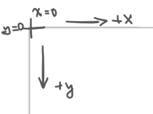
First, the pixels on the screen starts off with the origin point (0, 0) at the top left corner. But the the center of the Mandelbrot set fractal, where the cool actions are at, is at (0, 0). This means that we have to translate or we will only see a small corner.

Secondly, as seen above, the “main features” of the fractal only span from -2 to 1 on the real axis, and -1 to 1 on the imaginary axis. A 1-to-1 mapping would make the whole rendering of the features in a couple of pixels, literally!
Thus proper scaling and translation is required:
map screen_x from (0, screen_max_width) to (-2, 1)
map screen_y from (0, screen_max_height) to (-1, 1)
Luckily, the Mandelbrot set we’re currently working here is vertically symmetrical, so we don’t have to flip the \(y\) axis (since on the screen, positive y is pointing down).
Putting everything together, we use nested loops to iterate through all screen x and y values.
for screen_x from 0 to screen_max_width do
    for screen_y from 0 to screen_max_height do
        x_0 = map screen_x from (0, screen_max_width) to (-2, 1)
        y_0 = map screen_y from (0, screen_max_height) to (-1, 1)

        iterations = mandelbrot(x_0, y_0)

        color_pixel(screen_x, screen_y, iterations)
We use the number of iterations as a value to determine the color of the pixel.
function color_pixel(screen_x, screen_y, iterations) do
    if iterations is max_iterations then
        color (screen_x, screen_y) to black
    else
        if iterations = 1 then color blue
        else if iterations = 2 then color cyan
        ...
What’s Next
We have just established the groundworks for the second part of this project, which is to actually program it onto the FPGA. In the next part, we will look into turning the above mentioned algorithm into hardware using basics of digital design: combinational and sequentail logics. Stay tuned.
-
https://en.wikipedia.org/wiki/Mandelbrot_set ↩