How to Train Your Motors: Week 4-9
Updated 2018-03-14
Last time, we’re left with a single motor with optical encoder setup and the motor was barely controllable. This post outlines the progress we have made since then.
TL;DR: Read the summary slide deck.
System Modelling
In order to better understand the behavior of our system and how it responds to potential controller inputs, we need to have an accurate representation in the simulator. The simulator model is composed of motors, controller, and any electrical and mechanical dynamics involved.
Note: Dr. Leo Stocco’s method of finding motor parameters is online here
Motor Parameters
The motor parameters refers to the electrical and mechanical dynamics involving just the motor component.
Electrical
The motor can be modelled electrically as a equivalent resistor, inductor, and a voltage source with opposing polarity. Capacitances are small and can be neglected.
The resistance + inductance can be measured as complex impedance by sampling the transient behavior. Specifically, we apply a small current to the motor, and measure the time constant.
The rotor produces a back EMF that opposes the applied voltage. The faster the rotation, the bigger the back EMF voltage. We assume this relationship is linear, thus only a constant Kv is required.
To obtain the back EMF constant, we apply a constant voltage to the motor and measure the rotational speed. The voltage produced by the spinning rotor is applied voltage - voltage loss due to resistance. The ratio of voltage and RPM is our Kv constant.
Mechanical
The moment of inertia, J, contributes to the torque load due to mass. Since the mathematics are very similar, J can be obtained in a similar fashion to the electrical parameters - by observing the transient response and calculate from mechanical time constant.
For B, the friction coefficient, which contributes to the torque due to kinetic friction, we take torque / speed at no load conditions (conditions where nearly all torque is due to speed).
We didn’t attach any springs and the cogging behavior of the motor is neglegible. Therefore spring constant K = 0.
Lastly, the torque constant is determined by applying conservation of power. Power in = Power out; power in = voltage x current; power out = torque x speed. Knowing the power in and speed, we can find torque and ultimately the ratio of torque to current, Kt
Current Driver
The current driver is a bit more complicated because of its non-linear characteristics. Thus we observed it as a SISO system with the voltage as output and PWM as input. We noticed that voltage output (thus speed of the motor) does not increase linearly as PWM increased. So we ended up approximating the current driver as a inverted decaying exponential.
System Verification
To verify our system model, we look at the open loop and close loop responses and how they match with the real open loop and close loop response. Then we adjust our model accordingly to account for neglected variables.
Open Loop
For the open loop test, sampling position versus time would be pointless because the data is hard to analyze. This is because we have two poles at zero and thus the output given a step response input is a linear graph.
For the above reason, we look at how speed responds (taking out one of the pole by derivative). The speed is sampled by sampling change in position in the controller timer interrupt service routine (ISR) as I will explain later.
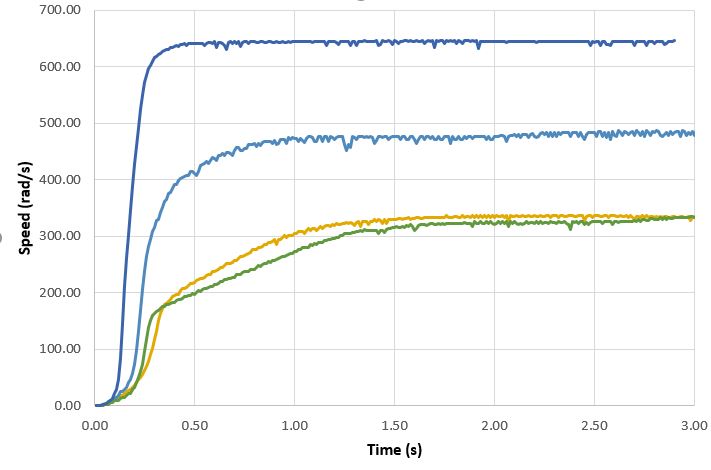
Here we observe the transient, open loop behavior of speed when we apply a PWM step.
Close Loop
The close loop response tests consists of three tests: P control, PD control, and PID control. This ensures that given that same PID, that the real system and the simulated system would behave similarly.
Controller
Microcontroller
We are using the Arduino systems which houses the ATMega328P microcontroller running at 16 MHz.
For our purposes, we need to use timers interrupts to ensure that the control frequency is fixed at all times. We allocate timer 1 for our needs but this also means that PWM is no longer available by default on digital pins 9 and 10.
Thus, we had to remap our pin usage:
| Port | Pin | Usage | PWM? | ADC? | PCINT? |
|---|---|---|---|---|---|
PORTD |
D7, D8, D9, D10 | Quadrature encoder input | no | no | yes |
PORTD |
D5, D6 | Motors output enable | yes | no | yes |
PORTC |
A0, A1 | Motors direction control | no | yes | yes |
PORTC |
A4, A5 | Motors position homing limit switch | no | yes | yes |
PORTD |
D11 | Laser control | yes | no | yes |
Using this layout, we have six pins: A2, A3, A6, A7, D2, and D3 pins to do whatever we like. Potential peripherals include LCD or LED displays, switches / buttons, and wireless modules.
Position / Velocity Detection
The position of the motor shaft is determined by counting the pulses produced by the slot detectors. As far as the controller is concerned, the speed is sampled at the constant control frequency. The position is the velocity summed up. These variables are later used to determine the motor gains.
I will probably post a follow-up blog on the quadrature encoder logic with more details.
Homing
To ensure that the motor will always operate in the same range consistently, we implemented homing procedures for the motors.
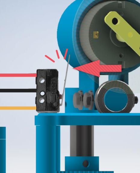
For the yaw motor, we installed a limit switch at the end of the motor’s range of operation angles. The switch will become active when the motor moves to a certain angle.
We haven’t implemented anything physical for the pitch motor, but we’re thinking of just making wire contacts outside the motor.
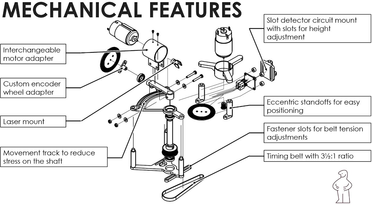
Mechanical
The mechanical parts have been updated to support the final product’s operation. There is a timing belt system that has a 3.5:1 ratio that drives the yaw motion.
This enables us to have 3.5 times more torque, something that we definitely could use to drive heavier loads. Furthermore, since it reduced the output angular speed down by 3.5 times, that means we get 3.5 times more resolution from the encoder wheel as well.
Next Steps
For milestone 3, we obtain the custom built motors by our motors team. The two teams form a single 4-person group and we work to integrate EVERYTHING together.
Here is an outline of what needs to be done (possibly in no particular order):
- Obtain motor parameters for our own motors
- Design new mechanical parts to put everything together
- Custom PCBs to include current drivers and logic ICs
- Update system model
- Update controller software
- Retune PIDs