How to Train Your Motors: Week 1-3
Updated 2018-01-25
First, let me introduce our project course, ELEC 391. This year we are building 2-DOF motor controlled laser pointer that is fast enough to draw images. The entire project is split into two teams: motor and control. The motor team is responsible for constructing good motors from scratch, using nothing but materials found in the lab or off the shelf. The controls team is responsible for running simulations, designing motor mounts, joints, and programming the controllers. I am on the controls team.

The project is also split into three milestones. Milestone 1: demonstrate some work-in-progress components and control systems. Milestone 2: the individual components should be more or less finalized. Finally, milestone 3: the entire integrated system should be working as designed. We’re still a week and a half from milestone 1.
Here are some of the progress we have made so far.
Motor
Version 1
The initial proof-of-concept was made of scrap wires and a single piece of magnet taken from a hard drive. It is more to confirm our understanding of theories such the right hand rule, Ampere’s law, etc.
Of course, since it only has one core, it doesn’t have a commutator and relies on the momentum to keep it spinning.
Version 2
The second working version uses 3D printed stator shell and rotor core. This time, five poles and coils are used. Thus 5 commutator connections.
We used stranded wires as brushes to provide current to the rotor; however, because the each strand of wires are so thin and are supplying so much voltage, we observed sparking and welding. Therefore dramatically increased friction. At top speed, the motor draws 2.0V and 4.0A, the top limit of the power supply!
Problems: Even with the bearings attached to the rotor shaft, the rotor core and windings are too heavy, thus an relatively large amount of torque is required to start rotation. The magnets were not providing a strong enough magnetic field. The commutator was rough and caused friction. The brushes were welding to the commutator. Finally, The current draw was too high (possibly due to small number of turns and small magnetic field).
Version 3
The version 3 was much bigger than version 2. This is mostly to resolve the frustration of working with magnets by allowing us to have more space to work with inside the stator shell. This time, we used eight 10mm x 5mm x 60mm neodymium magnets for the field. This made the motor to spin much faster.
Problems: The magnets were too strong and was difficult to install inside the stator shell. The magnets were too fragile and shatters too easily.
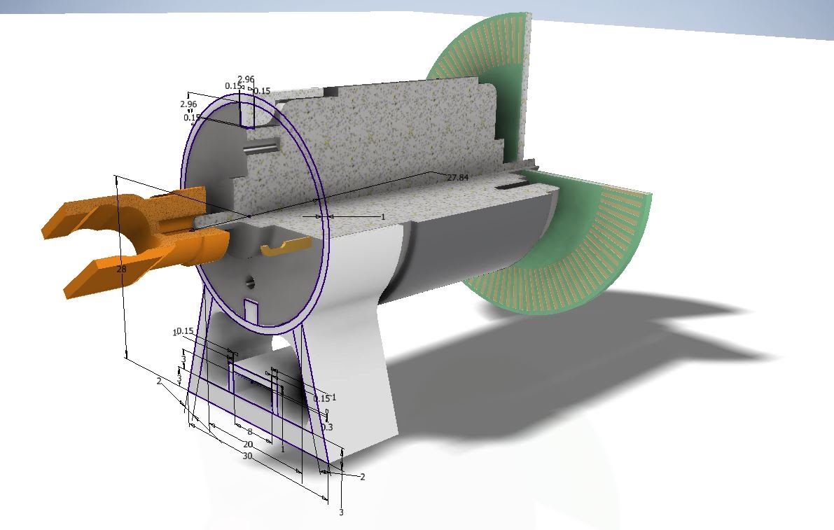
Version 4

In this version, the stator shell is redesigned to have slots for magnets. This way, the magnets slides in and won’t affect the position of other magnets while still providing a strong magnetic field. The diameter of the shell is shrunk to be closer to the rotor core.
The stator is designed to hold more windings while being lighter. And the commutator is extended to reduce roughness.
Controls
Microcontroller
The first thing that we need to do is pick a microcontroller. Of course, the no-brainer choice is an Arduino. We chose Arduino Nano to prototype for now since it uses the same microcontroller as Arduino Uno (ATMega328P) but is much smaller and easier to work with on a breadboard. It also takes up less footprint in a 3D printed case (for future milestones).
Simulation
Meanwhile, a SimuLink model is created to model the mechanical and electrical systems of the motors as accurately as possible. This is useful for tuning the control systems in the future.
Sensor
To obtain the current angle of the motor shaft, we need a rotary encoder. First we tried the mechanical rotary encoder which is essentially a pair of brushes action as commutators on some spinning disk.
To test, the sensor is hooked up to a debounce circuit, which is essentially a low pass filter. Then it is connected to the Arduino pins 2 and 3 because they support hardware interrupts. Every rising and falling edge of encoder output A and B triggers an interrupt. There are 24 slits on each revolution of the encoder wheel, that means 96 interrupts are triggered per revolution of the rotary encoder.
In the firmware, attachInterrupt() function is used to connect the interrupt to the right interrupt service routine:
attachInterrupt(digitalPinToInterrupt(encoder_A_int_pin), encoder_ISR, CHANGE);
As it turns out, the mechanical encoder SUCKS! It did okay at low speed, but at high speeds, it’s practically unusable. The encoder also produced unwanted signals under vibration, which is not that uncommon.
We are currently investigating into integrating an optical rotary encoder which is much better. The optical encoder eliminates friction and allows faster speeds.
Motor Driver
The L298 motor driver chip is used as power electronics. The digital input signal essentially breaks down to three for each motor: Direc1, Direc2, and Enable.
The Direc1 and Direc2 input signal determines the direction of rotation of the motor. If both are off or on, the motor won’t spin. The Enable input signal is an “analog” (PWM) signal. This controls the speed of the motor.
Mount & Test Bench
To hook up the motors and the encoder together, some kind of test bench is needed. First, all existing components are modelled in CAD programs, then new parts are designed and assembled in CAD programs.

The parts are 3D printed, assembled, and tested. In each iteration, the mechanical parts are improved.
The first prototyped (actually Mk2) test bench had a direct coupling between the motor shaft and the rotary encoder, which is mounted to a plate. This version did not work very well and immediately failed because the misalignment of the shaft and the encoder axis caused stress on the 3D printed part and produced a lot of friction. The part worn out very quickly.
The second version uses a gears with gear ratio of 1:1 instead of direct connection. This allowed the shaft to turn smoother, but still has a lot of friction. The meshing of the gears was also quite difficult to accomplish using 3D printed parts.
Since from now on, we are using optical encoders, the third version is completely redesigned. Since the encoder disk is too large to be fitted on the back of the motor, we flipped the motor around and instead plan to have laser mounted on the “back” side of the motor.
This version hasn’t been made yet because my 3D printer broke down :( so I hope this works okay.
A lot of progress has been made, but we still have a long way to go for a minimum-viable-product for milestone one.